Pico Systems
Universal PWM Servo Controller
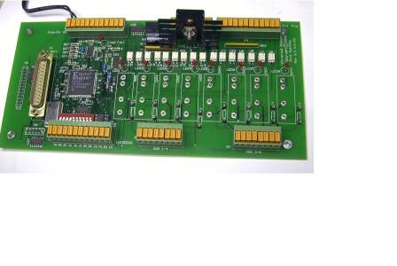
| the PWM controller board |
PWM controller, power supply and 4 PWM amplifiers |
 |
 |
Advantages:
- One board control solution for up to 4 PWM-input (digital) Servo Amplifiers
(For Analog-input servo amplifiers, see PPMC )
- Has 4 axes of encoder counters on board, for closed-loop operation
- Has Emergency-Stop logic with watchdog on board
- Also replaces Opto-22 style board for 8 SSRs
- Has 16 opto-isolated digital inputs for limit and home switches, etc.
- Provides isolated power source for limit and home switches
|
3-axis block diagram 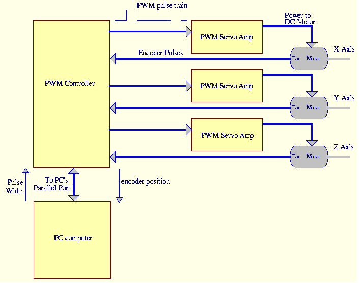 |
Complete PWM drive systems
Pico Systems is currently evaluating the price point at which we could
make complete drive boxes available. The big items here are electromagnetic
compatibility (FCC) and safety testing.
The Universal PWM Servo Controller is a small board with everything
needed to control a 2-, 3- or 4 axis machine tool with PWM-driven servo
amplifiers. It contains 4 PWM generators with variable PWM drive frequency,
4 digital encoder counters to follow the machine position,
16 channels of opto-isolated digital
inputs, and 8 positions for Solid State Relays of your choice to
be mounted. It is connected to a computer by the parallel port.
The parallel port must be at least capable of bi-directional exchange
of data, but EPP or ECP modes give the best data transfer rate.
The digital I/O section also implements emergency stop logic.
There is an on board watchdog timer, which can be set to cause an
emergency stop in case the computer fails to update the PWM generators in a
timely fashion. This could shut off the servo amps, spindle
motor, coolant, etc. For machines with more than 4 axes, 2 or more
boards can be used together.
The computer reads the position from the encoder counters and computes
a new PWM duty cycle to send to the PWM generators. This takes only
about 50 uS on a 333 MHz Pentium II, so that reasonable servo update
rates of 10 KHz could be made on such a machine. I usually use 1 KHz,
because that is all that seems needed for machine-tool type applications.
The PWM generators divide a 10 MHz crystal clock by a minimum of 2 up to
216-1, which comes out to 5 MHz down to 153 Hz.
A PWM frequency of 1 to 100 KHz is practical, and can be selected to suit the servo amplifiers.
The duty cycle of the PWM waveform can be programmed in 100 nS steps,
which is 1% at 100 KHz, but .2% at 20 KHz. The PWM and direction outputs
can source or sink 12 mA to drive opto-coupled amplifier inputs.
The encoder counters keep a continuous watch over the encoder signals
and can count up to 300,000 encoder counts/second, per channel. (The rev
5.x and later boards have an adjustable digital filter so that counting
above 5 MHz can be performed.)
They can also sense the
index pulse from an encoder which has this feature. This can be used to more
precisely locate the home position. If the encoder
has no index channel, connect the index input (Z) to A.
The digital input section has 16 optoisolators which can sense
the condition of switches, relays, pressure switches, float
sensors, etc. to allow the machine to be stopped if a fault condition
occurs, sense when an axis is close to the travel limit or home
position, etc. The board provides isolated 5V power to power
the switches and/or sensors.
The digital output section provides sockets for up to 8 Opto-22
compatible Solid State Relays to be mounted directly onto the
board. These sites are left unpopulated to allow the user to
select SSRs with the output configuration and current capacity
needed. A terminal strip is provided for connection to the
outputs of the SSRs. LEDs monitor the command signal to each of
the SSRs.
The last digital input is configured to monitor an emergency
stop chain. A series circuit of normally-closed switches breaks
the continuity of the circuit when an unsafe condition or problem
develops (ie. spindle motor stall, servo amp overheat, lube
level low, manual E-stop switch activated, etc.) An analog timer
circuit can also monitor the flow of commands from the computer, and
if the computer ceases updating the rate generators, then an E-stop
can be caused. The E-stop condition turns off all signals to
the solid state relays, as well as stopping the PWM generators,
to bring the machine to a safe stop.
This boards contains a power regulator that produces all power needed
by it from a provided 'wall-wart' type plug-in power supply.
The Universal PWM Controller takes advantage of the IEEE-1284 hardware signalling
protocol, allowing multiple register addresses to be selected and
transfers accomplished with minimum CPU overhead, and maximum
data transfer rate. This requires a parallel port that can
operate in the ECP or EPP mode. A male-female DB-25 cable specifically
designed for IEEE-1284 compatability is required.
Note: You MUST use a cable marked "IEEE-1284 compliant" for this system to work reliably.
Also, if using a PCIe parallel port card, it has been discovered that Startech, SIIG and Rosewill cards with the OXPCIe952 chip will not work with LinuxCNC versions before 2.7.8 (March 14, 2017). (PCI (not express) cards from SIIG have worked fine for years.) The Saba PCIe card with the NetMos MCS9900 chip has been verified to work, as well as other PCIe cards with the MCS9900 and MCS9901 chips.
Drivers for the EMC CNC motion program are included on
all CDROM releases of EMC.
Pico Systems is currently delivering this board at an end-user
cost of US $250.
Sample configs files for LinuxCNC using the Universal PWM board
Sample configs files for LinuxCNC using the UPC with the spindle DAC
Sample configs files for LinuxCNC using the UPC with 8 extra digital outputs
Sample configs files for LinuxCNC using the UPC with Spindle Sync for threading
Connector Pinouts for the Universal PWM board
Register Definition for the Universal PWM board
Switch Settings on the Universal PWM board
Parallel port compatibility and options
Download Linux diagnostic program
for Universal PWM Controller.
How to install and use the diagnostic program.
Sample wiring of the Universal PWM board
Sample wiring of the Universal PWM board with the PWM Power Switch
Dimensional drawing of the Universal PWM board
Price List
You can contact Pico Systems at :
(314) 965-5523
    or
543 Lindeman Rd.
Kirkwood,  MO  63122
    or
elson@pico-systems.com