Anyway, the old Excellon drills use WestWind air bearing spindles, made in England, and also definitely top of the line. These particular units are directly driven by coaxial 3-phase induction motors. (WestWind also makes air turbine spindles.) The motors were in great shape, but I needed a source of high-frequency 3-phase power. My old and cheap variable speed drive croaked, so I got a better one, made by Magnetek, which happens to go up to 400 Hz. That would get a 2-pole motor up to nearly 24,000 RPM, which is pretty good for small-hole drilling in composite laminates. So, I reprogrammed the Magnetek for the particular characteristics of the spindle motor, and had some trouble with it. After a few calls to Magnetek, they figured out I needed series inductors because of the low inductance of such a high frequency motor. This did the trick, and the spindle ran up to about 24,000 RPM at 400 Hz.
So, I then needed a method of mounting it. I decided to just clamp the spindle to the side of the Bridgeport's quill, as the quill travel needed for engraving and circuit board drilling is very small. But, the spindle must be EXACTLY parallel to the quill stroke, or it will break those tiny circuit board drills. So, I used the CNC system to make two plates out of some 1/2" aluminum bronze sheet I have from a gigantic (4' diameter) disk drive I scrapped years ago. I cut both plates inside and outside with them clamped together on the CNC mill, and then bored the holes for the quill and high speed spindle to the correct diameter, all in one setup. This assured the holes in the two plates were exactly the same distance apart, thereby preventing any tilt in one direction of the spindle. I made a spacer to hold the two plates rigidly in alignment, and then set it all up on the machine. I ran the quill up and down while reading along the side of the high speed spindle with a dial indicator. The natural alignment of two cylinders clamped in two (or really, 4) holes self aligned the whole works so no adjustment was needed. I then tightened the clamping screws that would lock the entire assembly permanently in alignment. I have had it on and off the Bridgeport several times, and the alignment is solidly repeatable.
I have drilled holes as small as .018" with this setup, and haven't broken a .018" drill yet! That's final confirmation that the alignment of the spindle rotation axis is coaxial with the feed.
| |
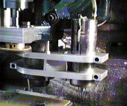
Here's a close-up of the spindle motor and the bracket that mounts it to the Bridgeport quill. |
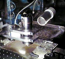 |
This is a wider view of the whole setup. The fixture plate I use for drilling PC boards and engraving plastic nameplates, etc. is also shown in this picture. |