 |
I have converted one of the ubiquitous minimills to CNC. I have a CNC Bridgeport, so I got this machine
mostly to carry to shows, but also for some testing of parts for smaller machine conversions. Here it is set up at a friend's
shop during an open house, you'll note it has different motors than in the later pictures.
|
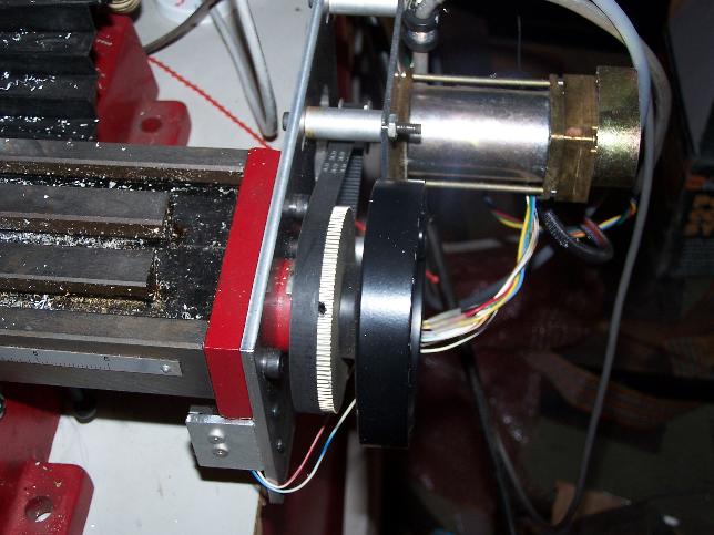 |
Here is the X axis mount. The motor is a Pittman brushless motor, fitted with an MXL pulley.
The mounting holes are slotted so the belt tension can be adjusted. The mounting plate is attached
through the bolt holes for the original bearing bracket. Longer bolts were used. The large pulley
was modified on a lathe to remove the extended hub and hollow out one side slightly to best fit over
the bearing bracket and inside the existing handle. The ID of the pulley was bored up to fit over
the handle where the graduated dial went.
|
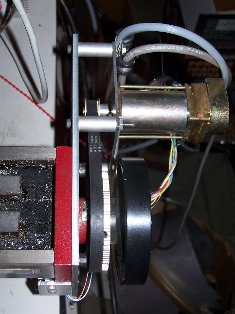 |
This is a top view that shows the motor pulley better. You can see one of the set-screw holes in the pulley.
These bear on a groove in the handle. I used two setscrews at 90 degrees, and carefully deburred the
edges of the hole to prevent damaging the belt.
|
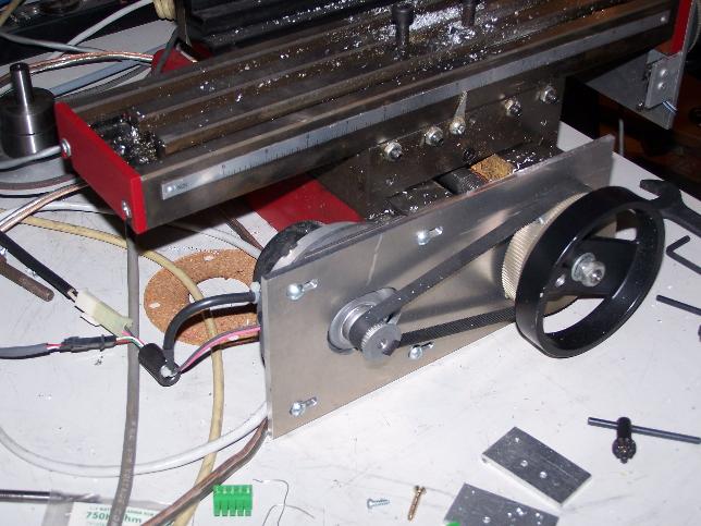 |
This is the Y axis drive, using a Japan Servo DC brush motor. This motor comes with a sintered-on MXL pulley.
Again, the mounting plate is slotted to allow belt tension adjustment.
|
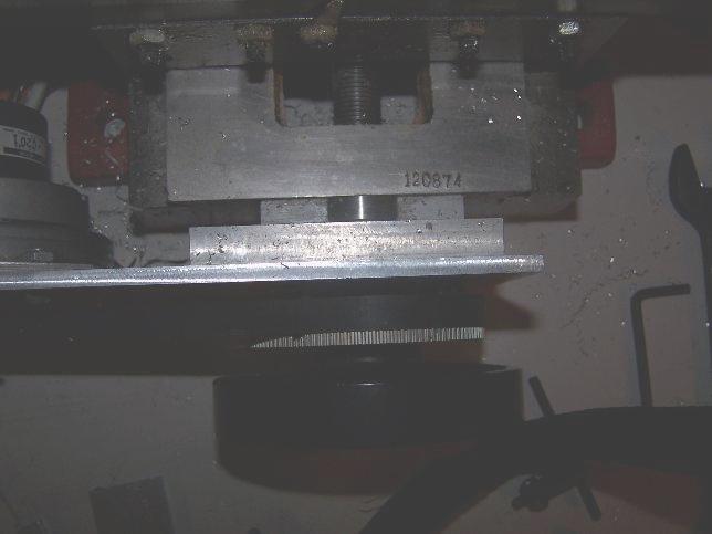 |
This is a top view of the Y axis drive, showing some of the more detailed steps in the conversion.
There is a bracket that IS the bearing for the Y leadscrew. Unlike the X bracket which has a pair of
ball bearings in it, this bracket has a brass bushing that is either too loose or too tight. I decided it could be bored from
both sides, using the original hole as the centering reference, to accomodate a pair of
ball bearings salvaged from some kind of disk drive. (I can't remember whether it was a floppy or hard
drive.) This modification worked amazingly well. You can see one of the ball bearing outer races
just below and to the left of the stamped serial number. There is a 1/2" aluminum plate that is
bolted to the front of the bearing bracket using the original screw holes. it has two countersunk
socket head cap acrews. That plate is tapped for the thinner plate that holds the motor.
The pulley is modified and adapted to the handle as on the X axis. The jam nuts for the handle also set
the preload on the bearings now, and can be made moderately tight. They used to have leave some play on the
screw or it would bind in the bushing. They would then creep up until the axis bound up.
|
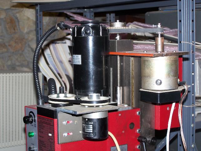 |
This is the Z axis drive, using a DC brush motor of unknown origin. I had to extend the motor shaft
to reach the top of the leadscrew. This machine originally came with a rack and pinion, which was
too coarse and had way too much backlash. I removed the rack and pinion components, and was able to
locate a TINY ballscrew on eBay. I still had to machine just a little metal off the back of the
assembly that slides on the column to clear the screw. I also made a bracket with a small bearing
to carry the bottom end of the leadscrew, and that is mounted in the original groove for the rack.
At the top end, I have a pair of ball bearings opposed against a shoulder in the center of the bearing
block, with preload applied through a threaded collar that can barely be seen below the sprocket.
(I used XL belts and pulleys here because I had them, mostly.) The bearing block has 4 bolts that go into
holes I tapped into the top of the column. The screws go through the motor mounting plate, too.
You can also see the spindle encoder that I use for threading operations. I now use this machine with a "thread drill" combined drill-tap to make tapped holes in my servo amp mounting plates in one operation. I also had to connect a servo amplifier to the spindle motor so it could be reversed under computer control.
|