 |
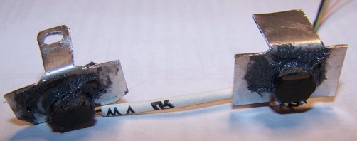
Here are a pair of the sensors, wired together with wire-wrap wire at the approximate spacing they will be in on the mill. The brackets are 0.030 aluminum with a hole drilled and filed to closely fit the shape of the back of the sensor. The back of the sensor has the magnet in it. The front of the sensor has the leads coming out toward the bottom, they are folded back away from the gear. The lettering and logo is on the front (sensing side) of the sensor. The sensors are glued into the holes in the brackets with PC-7 two-part epoxy, which is supposed to be tolerant of oil.
|
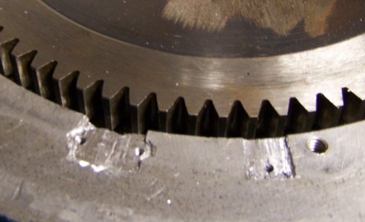 |
This is the top of the back gear gearcase, just above the main spindle casting. It is aluminum. I made very crude rabbetts to allow the mounting tabs of the sensor brackets to be below flush on the casting. I drilled and tapped some 2-56 holes for the mounting screws. I made the right rabbett wider than needed, so the bracket and sensor can be slid along the gear to get the right phase relationship between the sensors.
|
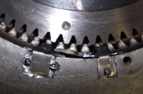 |
Here the sensors have been installed on the head. The wires are fed out through a hole I had previously drilled in the casting for a spindle speed sensor. The sensors are about 1 mm away from the tips of the gear teeth. When one gear tooth is exactly centered on one sensor, the other sensor should be centered about halfway between a tooth and a valley. This will set up the 90 degree quadrature relationship. I used an oscilloscope to check the phase relationship, but it could be done with indicator LEDs if you don't have a scope. You can also see the hole I drilled in the gear for the index sensor. This hole is about 1/8" in diameter and no more than .1" deep, just enough to trip the sensor. I made matching reliefs in the gear cover plate to clear the 2-56 screws that hold the sensor brackets in place. This was done by transferring marks from the screws and then drilling shallow holes with a 3/16" drill bit.
The bull gear has 81 teeth, so the encoder will give 324 counts per revolution.
|
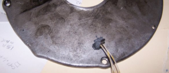 |
This is the cover for the back gear section. I drilled a hole in it far enough inward to be away from the gear teeth. I then filed the hole to accept another gear tooth sensor. After remounting the plate, I marked and drilled a shallow hole in the bull gear as seen in the above picture, so it would pass right under the sensor. I mounted the sensor so that it would protrude very slightly from the seating face of the cover plate. I did this on a surface plate, raising the edges of the plate with paper shims. I wanted to get no more than 1 mm clearance between the face of the gear and the face of the sensor. Make sure the hole is large enough so that the sensor wires do not short to the plate. I soldered extension wires to the sensor and ran the wires along the edge of the cover plate and out the same hole as the sensors on the gear. This sensor forms the Index (Z) part of the spindle sensor.
|